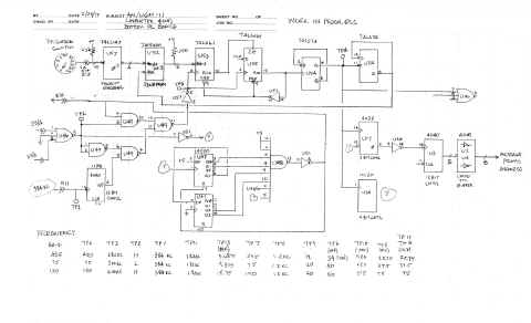
AN/UGM-11 (Wavetek 404) Notes from repair
- Crude and incomplete - but it was enough to get mine repaired and running
- Please send email if you have any
more info, schematics, manual, etc.
Here's what I vaguely remember from troubleshooting a couple of years ago ---
- The top PC board is mainly the tone generator - some LS163 4-bit
counters feed adders and then address a PROM
- This eventually addresses a 12-bit D/A (AD565) and AF output via a 741 op amp
(?) and Q1, Q2
The bottom PC board is the baud rate generator plus message generator
circuitry.
- U37 gets 3.xx mc in and divides it by 128 to 384kc output (TP1 = Test Point 1)
- U38 divides this by 128 to 3kc (for 75 Baud) which eventually shows up at TP3
- This gets divided by 40 (U53, U55, and U54) and shows up at TP4 at the bit
frequency.
- This gets divided by 8 by U17 and shows up at TP13 (Why 8 instead of 7? -
needs investigation)
- FINALLY, this signal drives U3, a 12 bit counter that addresses the
message PROMS (FOX, KWR37, KG14, etc.)
- I assume the PROM outputs feed a shift register or UART but don't have any
notes on this part of the circuitry yet
Some more notes from troubleshooting (2/17)
-
The DISTORTION switch S2 feeds a 74LS147 10-input priority encoder (U57)
which outputs 4 bits.
- These feed the 4 lower address bits of an IM5600 32x8
PROM (U52).
- Outputs 0-3 of the PROM preload a 74LS161 counter (U55). This
counter is clocked by pulses whose frequency depends on the baud rate setting
(test point TP3 - 1820 Hz for 45.5 Baud and 3000 Hz for 75 Baud)
- U55 counts up N ticks from the preload value to 15 and then
counts 0-15 before preloading again. So the preload happens every N + 16
ticks.
- IF the distortion = 0, then N should be 4 (preload = 1100), making 20
ticks total. N is changed to create the desired distortion.
- The output of U55
goes on through a little more logic to clock the serial output, increment the
address counters of the message PROMs, etc.
- My problem....
Somehow the output of my U52 PROM had changed from 1100 to 0100. So for 45 baud,
I was getting 28 clock ticks resulting in 30 ms bit times instead of 22 ms bit
times (test point TP4). I said "forget distortion" and wired bit 3 high.
HIGH LEVEL (60 ma loop) notes (2/17)
- There is no internal loop supply - you must supply a loop (probably 200vdc max) with
a series resistor limiting the loop current to 60mA
- There are two independent loops DC-1 & DC-2. Loop polarity doesn't
matter because there are bridge rectifiers on the switching transistor
outputs.
- DC-1 is switched by Q6 (2N3440) which is driven by Q5 (2N3440) which is driven by
opto-isolator U45 (TIL-111) which is driven by Q4 which is driven by Q3.
- DC-2 is switched by Q10 (2N3440) which is driven by Q9
(2N3440) which is driven by opto-isolator U44 (TIL-111) which is driven by Q8 which is driven by Q7.
- Q3 and Q7 are driven by a TTL-level bit stream selected by the MODE switch
(space, mark, reversals, FOX, etc.)
Operational notes (2/17)
- Set the OUTPUTS switch to BAUD for 45.5 and 75 baud serial - output is
7.00 unit code, not 7.42
- LOW LEVEL outputs are +/-5v for TEMPEST signaling.
- I don't know what the SATCOM outputs are for.
- Other settings of OUTPUTS can be used for AFSK audio output - these will
run at 75 Baud (green LED on)
- For UCC-1 audio output, set OUTPUTS to 85 shift and turn on desired UCC-1
channels
- My tones frequencies are off, so I still have a problem there to track
down - the sine wave audio out looks good though.

