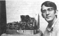
 With the new multi-speed provision for amateur RTTY, the Model28 reperforator-Transmitter or “RT” Set
should become quite popular. This is the model 28 version of the older FRXD. Most 28 RT sets come
equipped with three speed gearshifts on both the reperf and the T-D – allowing down speed conversion as
well as up speed conversion. Down conversion cannot be done with the “simpler” electronic speed
converters, as there is no provision made for storage. Converting from 100 WPM down to 60 WPM, for
example, requires storage provisions for four characters every second. To operate under these conditions
for any length of time requires a tremendous amount of storage. Giant
shift registers (available in MOS ICs) or large magnetic core memories could provide storage, but the electronics become a nightmare for
the average amateur. In the RT set, the paper tape is the storage medium. At ten characters per inch, you
can store quite a message in a few feet of paper tape.
Since most 28 RT sets come equipped with the 28 LPR typing reperf with the single magnet selector
mechanism, which is a simple two wire connection into the loop, the bulk of this article will describe the
connections for the LAXD “creep-head” T-D.
In talking with several amateur RTTY suppliers, it appears that most amateurs prefer the simple single
contact LXD T-D to the model 28 multi-contact T-Ds. The model 14 T-D is a multi-contact T-D, the main
difference being that all of the connections between the transmitter (or sensing head) and the distributor
were made at the factory.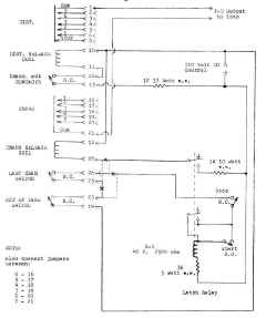
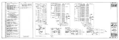
Hooking up the LAXD is simply a matter of connecting the transmitter output (Parallel output) to the
distributor input (parallel input), taking the serial output from the distributor, and connecting the control
circuitry. The circuit diagram shows a “deluxe” arrangement as far as the control circuit goes, and this can
be simplified if you wish.
The latching relay circuit shown is required if you want the T-D to shut off if it should ever run out of tape
completely. You can mount the start and stop buttons conveniently at the operating position and remote
locate the rest of the noise generating machinery! For K-1, I used an Allied T154CC-CC, which has four
sets of contacts. One of the extra sets can operate a light to tell you when the T-D is operating. Another
light can be operated by the low tape switch in the reperf tape supply reel so you know when you are about
to run out of tape.
It is important to observe that the transmitter auxiliary contacts are in series with the distributor release
coil. These contacts are normally open, and will close for a short time after the transmitter has “sensed” the
holes in the tape and stored the combination, allowing the distributor to operate for one cycle distributing
the combination stored in the transmitter. This connection must be made or else the unit will send only
garble if it sends anything at all Attention is called to the fact that the last character switch, the out of tape
switch, and also the added stop switch are all normally closed.
One change, which can be made, is a matter of preference. Using the circuit as shown in the heavy
lines, the T-D will shut off after it has read the last character punched, and will not read again until the start
button is pressed – providing that the reperf has punched more tape to be read. If the heavy lines are
broken at the three Xs and the dotted lines added, the T-D will stop reading after it has read the last
character punched, but now if more tape is punched, but now if more tape is punched, and the stop button
has not been pressed, the T-D will start reading the tape again and will continue until it reads all the tape
again or until the stop button is pressed.
If you don’t care about out of tape shut off, simply delete the relay, don’t use the out of tape contacts, put
the last character switch (dotted lines) in series with the transmitter release coil, and finally replace the
relay contacts in series with the transmitter release coil with a SPST switch which becomes the T-D
operate switch. If you don’t use the latching relay, and the T-D should ever run out of tape, it will send
“letters” continuously until shut off manually.
The pin numbers given are for the Amphenol 26-4401-32S connector on the LAXD-1, and will probably
be good for most units. If you are not sure, a simple ohmmeter check can be made. Please note that the
110-volt DC input is a control voltage source and not the loop. The loop supply can be used if it is hefty
enough (allow about 300 ma. For the control circuitry), but a separate control power supply would be best.
The only connections made to the loop are the two T-D output wires hooked in series with the printer etc. If
heavy arcing is experienced at any of the control contacts, they should be shunted by a series RC arc
suppressor network.
The basic hookup for the LBXD T-D is essentially the same as shown for the LAXD. The elaborate out
of tape circuit is not required with the LBXD since its out of tape switch is spring operated rather than cam
operated as in the LAXD. Also for those with a LBXD or another LAXD the transmitter from one T-D can
operate the distributor in the other unit or vice-versa. Simply replace the transmitter output-distributor input
jumpers with a multi-pole two position switch. Be sure to bring along the transmitter auxiliary contacts and
the release coils.
My 28 RT set is very similar in appearance to the older FRXD. Other units came mounted on a
tape-handling stand, which includes large tape take-up and supply reels as well as an intermediate
storage bin. Additionally, the LAXD can be mounted in the 28 ASR providing an RT set within the cabinet.
I built an intermediate storage bin patterned after the Teletype Corp. unit from Plexi-glas and pressboard
and this hangs on teacup hooks below the shelf, which supports the RT unit |
